Wi-SUN tutorial
This tutorial provides guidelines on how to create your own Wi-SUN Field Area Network (FAN) mesh network and register your devices to Pelion Device Management.
Wi-SUN FAN has been designed for wireless outdoor networks, such as smart metering and street lighting systems. Its performance is optimized for large-scale networks rather than small networks. Therefore, when connecting the devices, be patient; the network formation takes time.
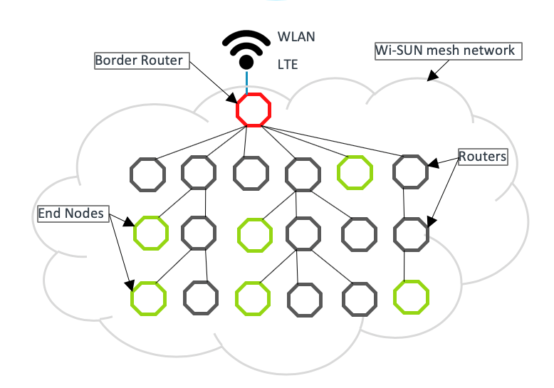 Network topology
Hardware requirements
To build a Wi-SUN FAN, you need the following Arm reference hardware:
-
Wi-SUN devices (for example, 10 pieces).
-
RF shields (for each Wi-SUN device and border router).
The default SPI SCLK pin configuration is D13. On the X-Nucleo-S2868A1, resistor R6 must be soldered instead of R11. For more information, please see the UM2405 user manual.
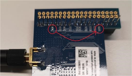 Resistor soldering to R6
 -
-
Ethernet connection (recommended) for the border router, with IPv6 connectivity with stateless address auto configuration (SLAAC) enabled.
-
LTE connection (optionally) for the border router.
- Quectel development board.
- LTE modem.
- SIM card with LTE connection supporting IPv6.
Note: You must ensure you use the correct variant of this modem to work in your country.
-
Required accounts
You need the following accounts:
Setting up and running the border router
To set up the border router:
- Clone the border router repository.
- Run
mbed deploy. - Select the target platform.
- Select the toolchain.
- Build with Wi-SUN configurations.
Note: Run mbed detect to list connected targets and supported toolchains.
As an example:
$ mbed deploy

$ mbed target DISCO_F769NI

$ mbed toolchain GCC_ARM

$ mbed compile --app-config configs/Wisun_Stm_s2lp_RF.json
If you are not using Ethernet, use configs for LTE backbone instead.
Running the border router application
-
Find the binary file
nanostack-border-router.binin theBUILDfolder. -
Copy the binary to the USB mass storage root of the development board. It automatically flashes to the target MCU. When the flashing is complete, the board restarts itself.
-
Press the reset button of the development board if it does not restart automatically.
-
The program begins execution.
-
Open the serial connection, for example with PuTTY.
You can find more details in the Nanostack border router instructions.
Tip: Use the same Mbed OS version in the border router and the application (Device Management Client).
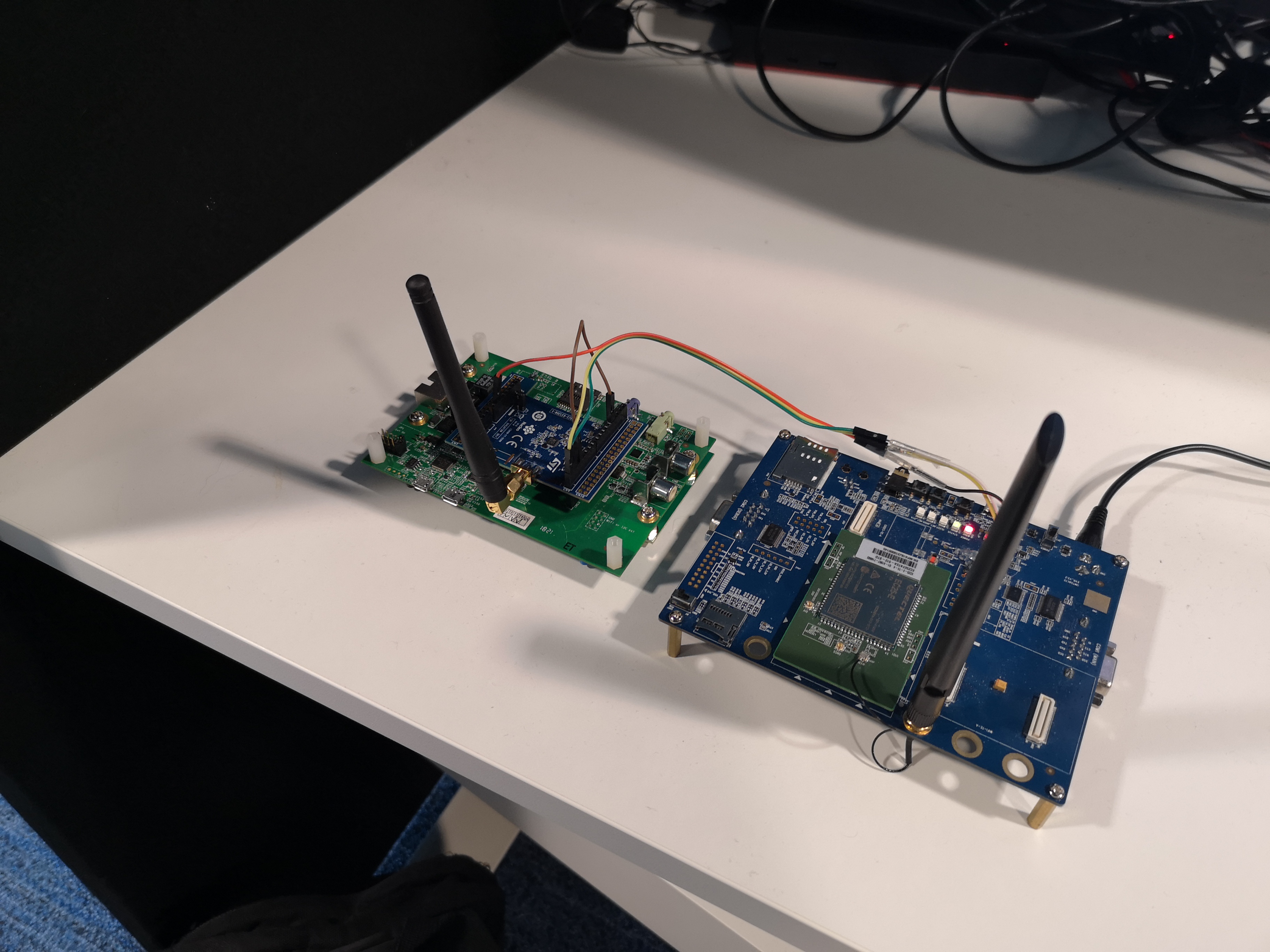 Border router with LTE backbone
Setting up the Wi-SUN devices and connect
Please follow the Pelion Device Management Client tutorial for the prerequisites and basic steps. The key difference is to use the Wi-SUN configuration file when compiling the client.
-
Copy the
configs/mesh_wisun.jsonfile on top of thembed_app.jsonin example root folder. -
Use the Wi-SUN certificate definitions file
configs/wisun_certificates.h, or generate your own Wi-SUN certificates (recommended) file to the same location. -
Ensure required Wi-SUN certificates (in file
wisun_certificates.h) are valid (WISUN_ROOT_CERTIFICATE,WISUN_CLIENT_CERTIFICATE,WISUN_CLIENT_KEY), and match the settings you are using with the border router. Invalid certificates or certificates that don't match prevent mesh network formation. -
In the
mbed_cloud_client_user_config.hfile, changeMBED_CLOUD_CLIENT_TRANSPORT_MODE_TCPtoMBED_CLOUD_CLIENT_TRANSPORT_MODE_UDPto use the UDP protocol instead of the default TCP.
Tip: Use the same Mbed OS version in the border router and the application (Device Management Client).
Note: When you go to production, please do not use the example Wi-SUN certificate files provided as is due to security reasons.
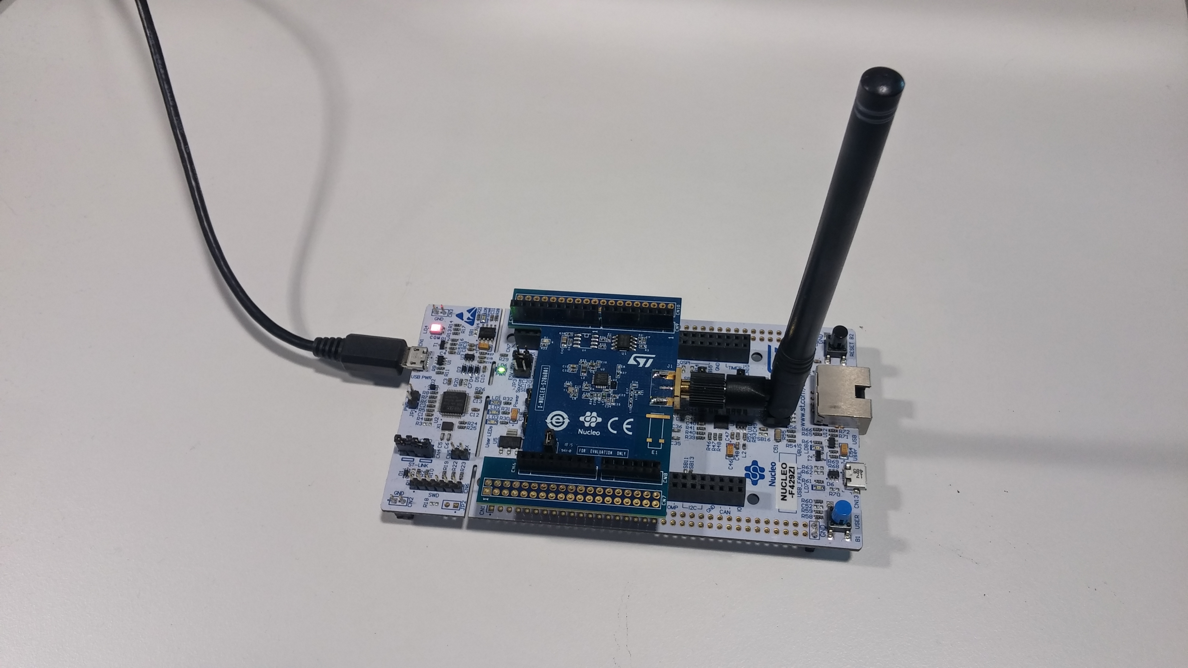 Wi-SUN device
Validating
To validate the formation of your Wi-SUN network and the registration of devices to Pelion Device Management, open the Device Management Portal, and check the devices have been registered:
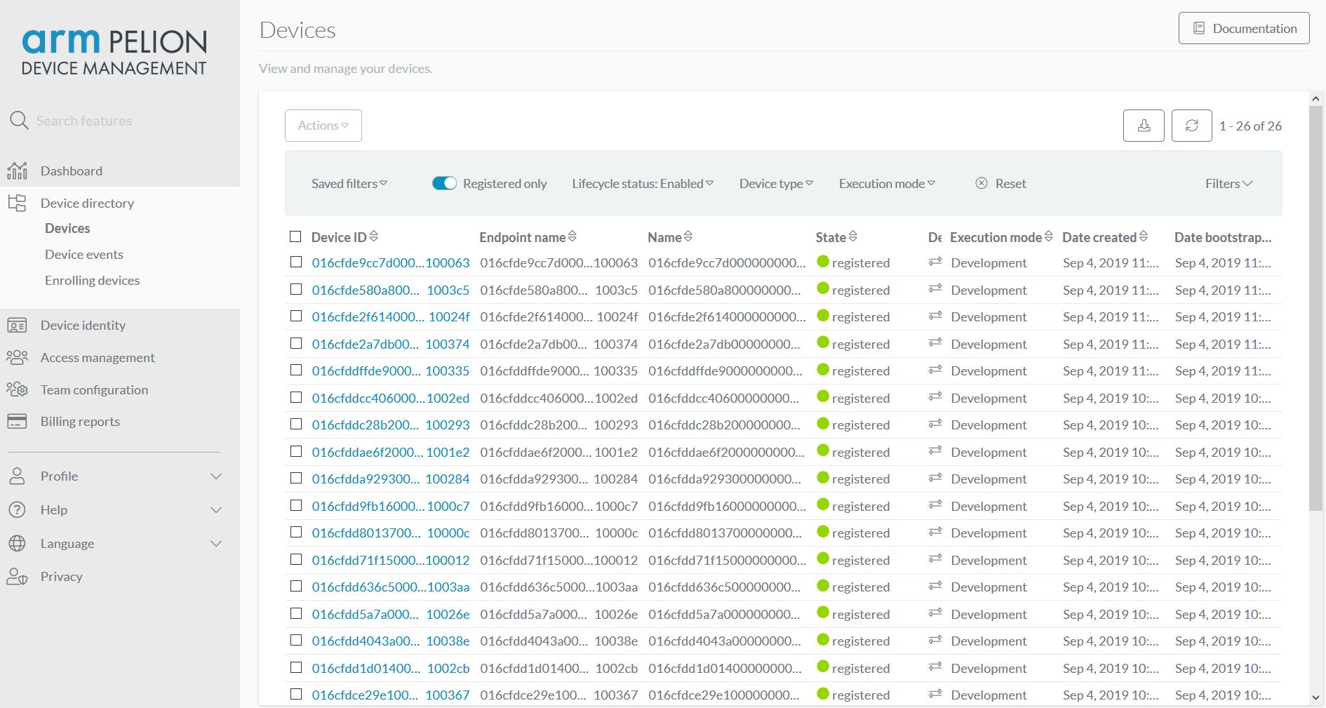 Devices in Device Management Portal
Troubleshooting
If the device does not register successfully to Pelion Device Management, check the soldering is done properly.
Enable traces in configs/mesh_wisun_S2LP.json:
"mbed-trace.enable": true
Then ensure you do NOT see this error in the logs:
[ERR ][s2lp]: Failed to change state from 0 to: 30
A Failed to change state error either indicates an antenna circuit failure or a communication issue between the S2-LP transceiver and MCU.
First, check your soldering, and make sure the resistor is properly connected to R6. If you still see the issue, the antenna may not be suitable for use with this configuration.