Building the circuit
First, build a basic circuit by connecting the RGB LED and the PIR sensor to the development board.
SD card
Note: Before you start, put the SD card in the SD card reader on your development board.
Izuma Device Management requires an external storage to store the identity of the device, and to store firmware updates. This external storage does not necessarily have to be an SD card (which is too expensive to put in a production device), you can also use internal flash or external SPI flash. To modify the storage layer, you'll need to modify the bootloader (see 'Section 8 - Firmware updates') and the application (see mbed_app.json in the connected-lights-cloud application later in this tutorial); which is not covered in this tutorial. More information is in the Device Management documentation.
Finding suitable pins
For the circuit, you need four digital pins. Three of these need to support pulse width modulation (PWM). Through PWM, you can control the amount of current flowing through a circuit, and you can use this to dim the colors of the LED on one of the three RGB channels.
To find pins that you can use, look at the platform page for your board, and find the pinout. The pinout defines the characteristics of the pins. For example, here is the pinout for the FRDM-K64F. In this example, you can use D5, D6 and D7 as our PWM pins:
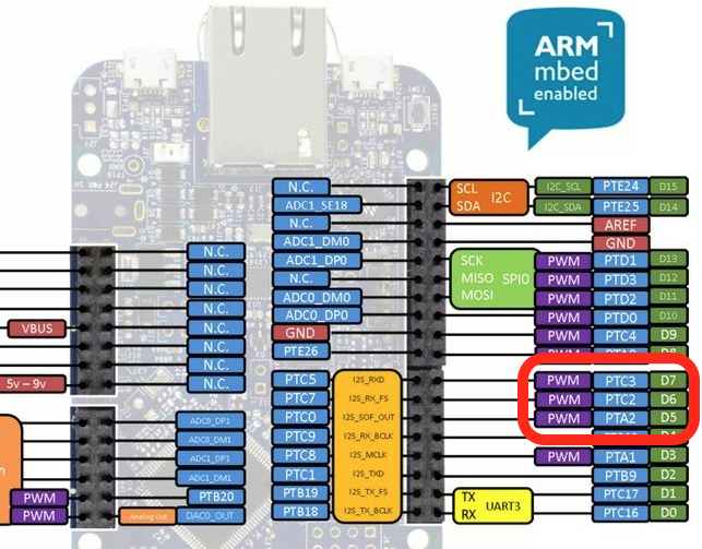 The pinout for the NXP FRDM-K64F, showing that you can use pins D5, D6 and D7 for PWM.
You also need a pin for the PIR sensor. This can be any digital pin, as long as it's not marked as UART (D0 and D1 on the pinout above). In this example, you can use pin D2.
If you do not have a PIR sensor available, you can use one of the on-board user buttons. This can be any of the available user input buttons, as long as it's not the RESET button. In this example, you can use pin SW2.
Note: In general, it's a good idea not to use any of the I2C and SPI pins for LEDs and basic sensors because connectivity shields (such as Wi-Fi) might need them.
Connecting the peripherals on a breadboard
Here is a diagram of hooking up the PIR sensor and the RGB LED to your board. Replace the pins D2, D5, D6 and D7 with the pins you found for your board. If you have a four-pin RGB LED, you must position the LED so that the longest pin is the second from the left. (Hold it like this.)
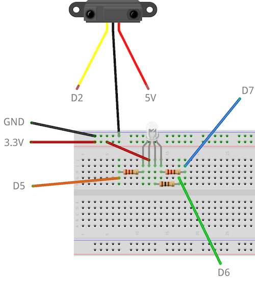
Note - common anode or common cathode LED: Four pin RGB LEDs come in two different types: common anode and common cathode. If you have a common cathode LED, connect the second pin to GND instead of 3.3V. If you are unsure, try both circuits and see which one works.
Note: If you're unsure of the pins on the PIR sensor and you have a sensor with a 'dome' on it, remove the dome. The PCB describes the pins.
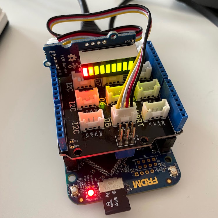
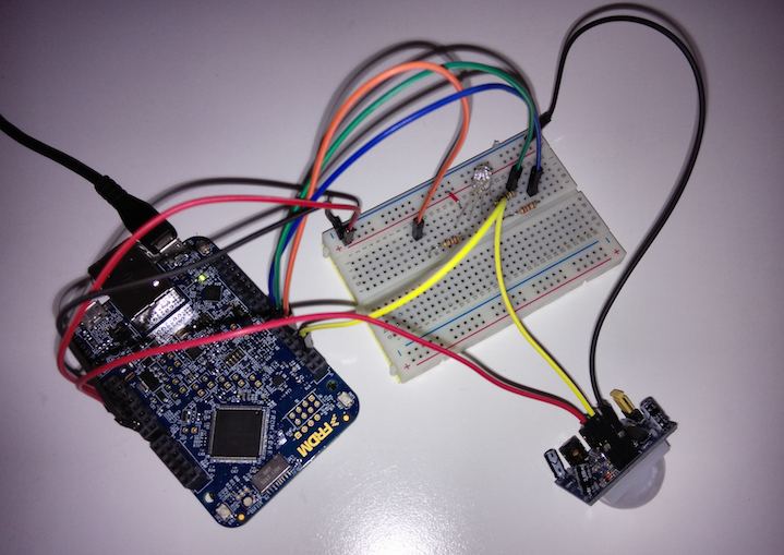
When you have connected everything, the circuit looks something like this:
If you are using the on-board user button and Grove LED Bar with Grove shield, the circuit looks like this: