Wi-SUN tutorial
This tutorial provides guidelines on how to create your own Wi-SUN Field Area Network (FAN) mesh network and register your devices to Izuma Device Management.
Wi-SUN FAN has been designed for wireless outdoor networks, such as smart metering and street lighting systems. Its performance is optimized for large-scale networks rather than small networks. Therefore, when connecting the devices, be patient; the network formation takes time.
For more information about Wi-SUN applications and the certification process, visit the Wi-SUN Alliance website.
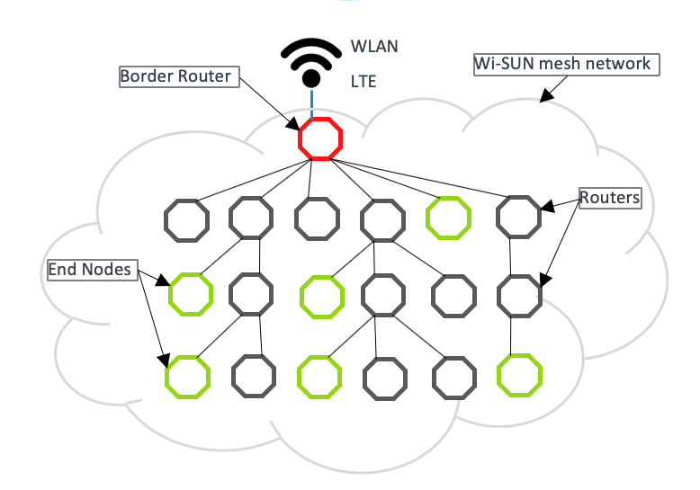 Network topology
Constraints
This Wi-SUN reference deployment is meant for indoor or laboratory environments:
- The reference deployment consists of uncased development boards.
- RF coverage is limited because the RF shield does not include additional amplifiers.
- For ease in setting up a small-scale network quickly, the example application referenced in this tutorial uses randomly generated MAC and Ethernet addresses. To obtain globally unique addresses when deploying larger-scale networks, see the section about globally unique MAC addresses.
- IPV6 Internet Service is required to connect a Wi-SUN network to the internet.
Wi-SUN certification
The Wi-SUN stack is certification ready and has been successfully certified by the Wi-SUN alliance. For more information, please see the Wi-SUN alliance certification guidance.
Hardware requirements
To build a Wi-SUN FAN, you can use this reference hardware:
-
Wi-SUN devices: Either NXP i.MX RT1050 EVKB or STM32 NUCLEO-F429ZI:
- For example, 10 boards.
- These are used as Wi-SUN router nodes in the mesh network.
-
Sub-1 GHz radio shields: X-Nucleo-S2868A2 or Microchip ATREB215-XPRO:
- One is required for each Wi-SUN device and border router.
- These provide the radio interface.
-
Wi-SUN border router: Either NXP i.MX RT1050 EVKB or STM32 F769I discovery kit:
- One required.
- By default, this tutorial uses the Ethernet connection for the backhaul network with IPv6 connectivity and stateless address auto configuration (SLAAC) enabled.
-
Optional LTE backhaul for the border router:
- Quectel development board.
- LTE modem.
- You need a SIM card with LTE connection supporting IPv6.
- You must ensure you use the correct variant of the modem to work in your country.
- This tutorial doesn't cover setup and use of LTE backhaul. For information, contact the Izuma team.
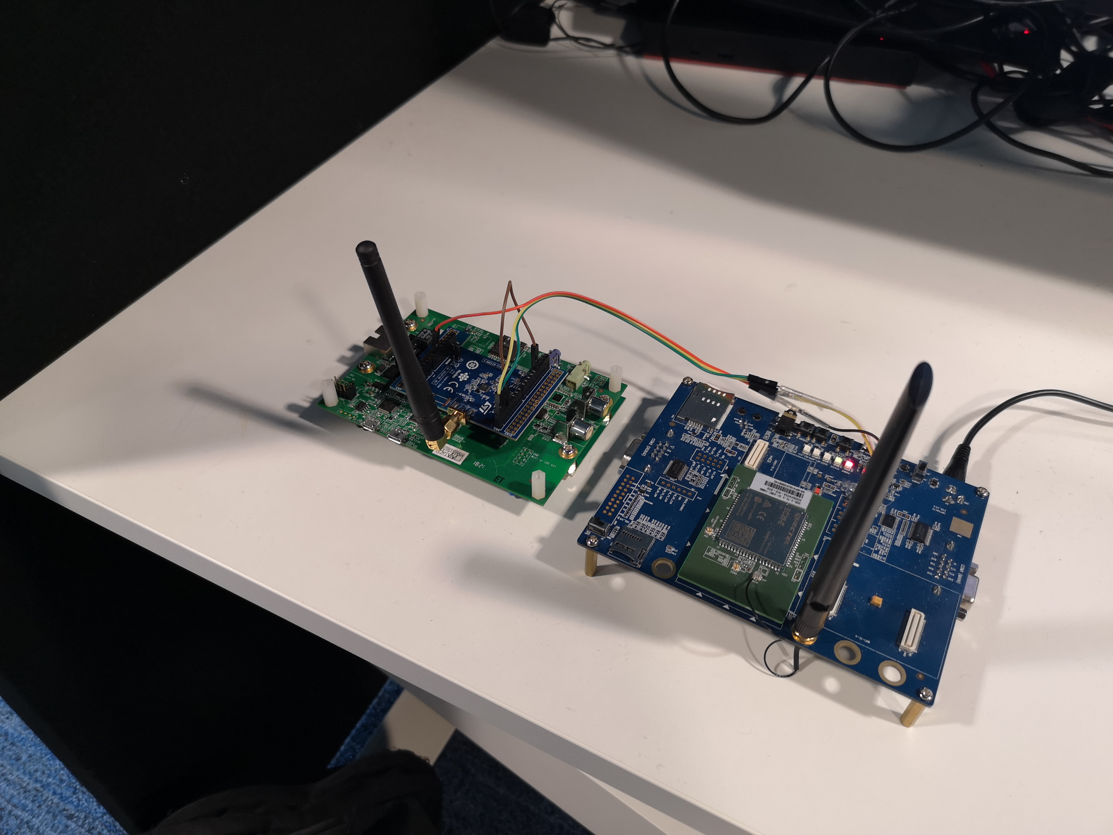 Border router with optional LTE backhaul
Storage requirements
Wi-SUN devices need storage for security keys and frame counters. This storage needs to survive the lifetime of device. If the storage is not functional, security authentication will occur every time device restarts.
Size requirements:
- Routers require 3KB storage. Data is written every 1,000 packets sent.
- Border routers require 3KB of storage and 300 bytes for each device connected to the network. Data is written to this storage daily.
Hardware setup
- HyperFlash is enabled on the board by default, but the stack uses the external memory connected over QSPI interface. To switch from HyperFlash to QSPI, follow the instructions in Section 2.2 and Figure 9 of the application notes.
- Arduino header SPI signals are not connected by default. To connect them, add 0 ohm resistors to R278, R279, R280 and R281 on the backside of the board.
- Arduino header I2C signals D14 and D15 are not capable of master mode. If this mode of I2C is needed, connect D14(SDA) to A4 and D15(SCL) to A5 and select A4 as SDA and A5 as SCL.
- For example, the Atmel RF driver by default uses this I2C to read MAC address from external memory. To disable MAC address read and to use a randomly generated MAC address, add the macro
DISABLE_AT24MACin your build configuration.
- For example, the Atmel RF driver by default uses this I2C to read MAC address from external memory. To disable MAC address read and to use a randomly generated MAC address, add the macro
-
Enable dual-bank mode on the STM32 F769I discovery kit:
- Connect the device using STLink-Utility software.
- Go to Target > Option Bytes. Uncheck the nDBANK option.
- Apply, and disconnect.
Note: You must configure the board to use dual-bank flash layout. The default configuration for F769NI is a single-bank mode. You can use the ST-Link utility to change the board to dual-bank mode by enabling the nDBANK byte option. Then, compile the application with
"target.flash_dual_bank": 1enabled. This is the default configuration for the Izuma border router.
RF shields
- Radio-type in application config:
ATMEL. - Not compatible with Arduino header.
- Connect XPRO Extension header to Arduino header as described in the image.
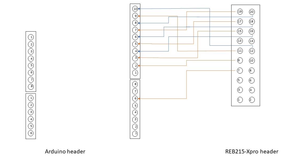 Connecting XPRO to Arduino header
-
Radio-type in application config:
S2LP. -
The default SPI SCLK pin configuration is D13. On the X-Nucleo-S2868A2, you must solder the resistor R6 instead of R11. For more information, please see the UM2638 user manual.
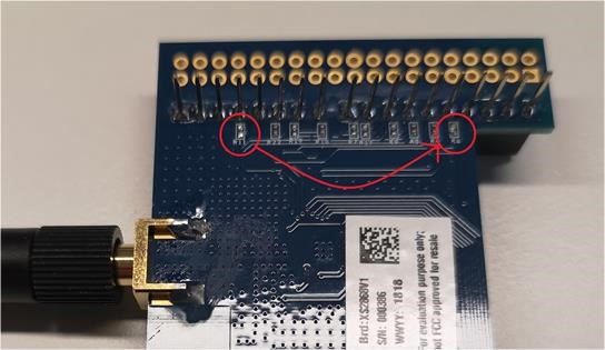 Resistor soldering to R6
 -
Attach the radio shield to the base board with antenna attached. Plug in a USB to the STLink port.
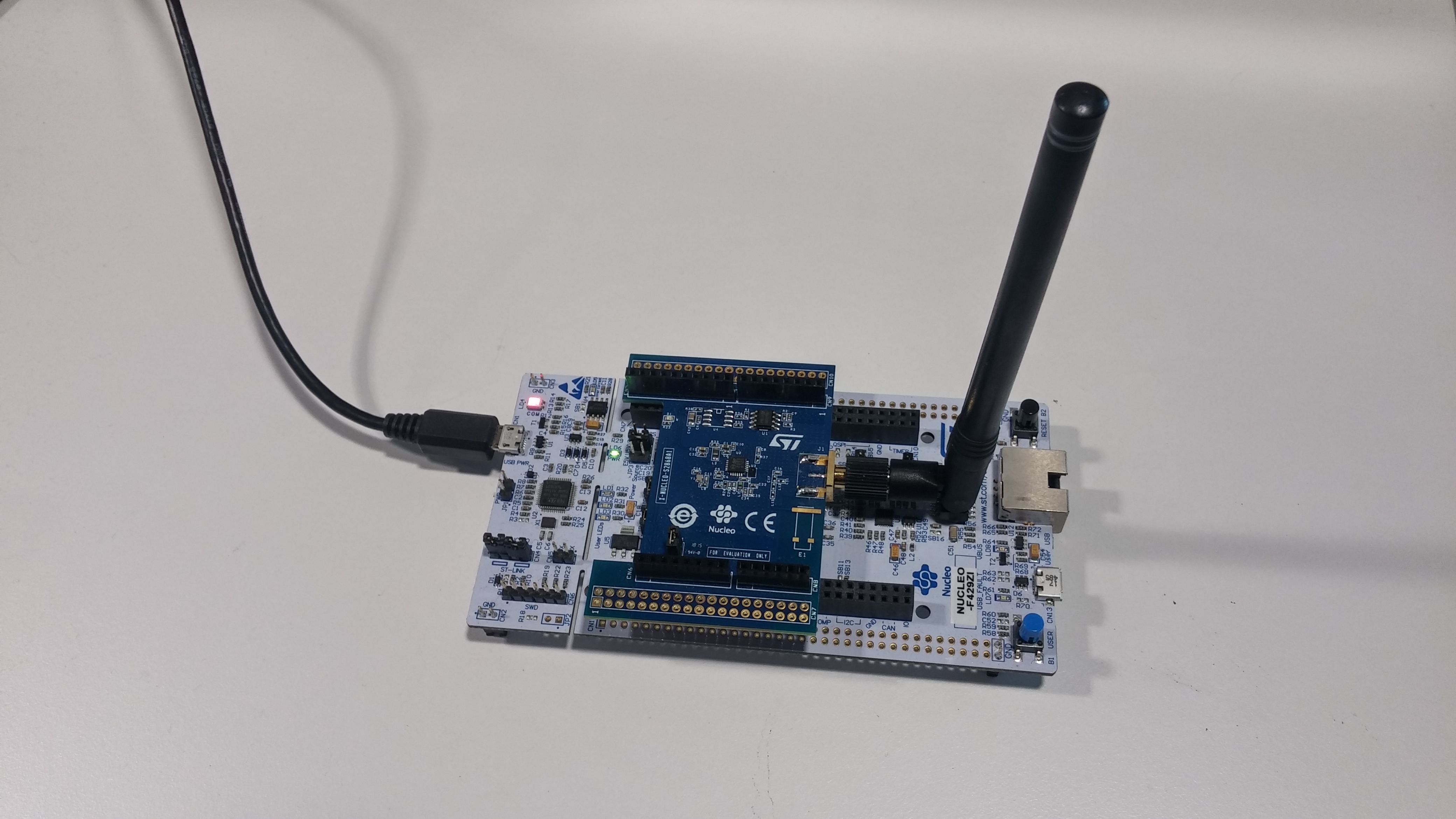 Wi-SUN device
Required accounts
You need:
Software setup
This tutorial uses Mbed OS-based applications.
To work with the Izuma border router application, you need:
- (Optional) Serial connection to your device with an open terminal connection (baud rate 115200, 8N1). This helps with debugging and confirming the client connects to Device Management and the Wi-SUN interface is up.
- Arm Mbed CLI installed. See installation instructions.
- Make sure all the Python components are in par with the
pippackage requirements.txt list from Mbed OS.
- Make sure all the Python components are in par with the
- An access key (with
Administratorsgroup privileges) for your Device Management account. - To configure the DISCO_F769NI internal flash memory layout to use dual-bank mode, download the STLink-Utility software. See required configuration steps below.
Setting up and running the border router
To set up the border router:
-
Clone the Izuma border router:
git clone https://github.com/PelionIoT/pelion-border-routercd pelion-border-router -
Deploy sub-libraries:
mbed deploy -
Select the toolchain:
mbed toolchain GCC_ARM -
Download a developer certificate from Device Management Portal.
-
Copy the
mbed_cloud_dev_credentials.cfile to the root folder of the application. -
Set the mesh network name in the
"mbed-mesh-api.wisun-network-name"field of thembed_app.jsonfile.The mesh network name can be any value, but it must be identical to the mesh network name you set for the network nodes.
-
Create update-related configuration and credentials using the
manifest-tool v2.4.1 or laterPython package:manifest-dev-tool init --access-key <Device Management access key>Note: If your host system Python version is 3.6, use manifest-tool version 2.4.1. Use version 2.5.0 (or newer) for a more up-to-date system. You can specify the version via:
pip install manifest-tool==2.4.1.Note: When you create a firmware update image for a deployed device, you must use the same update-related configuration and credentials (update private key, public key certificate,
update_default_resources.cand configuration files) you used in the original device firmware image. Therefore, you need to skip running this command because your environment is already initialized. -
Compile the application:
mbed compile -m DISCO_F769NINote: The default configuration already has support for Wi-SUN settings.
For more information, please see the Izuma border router repository.
Running the border router application
To run the border router application:
-
Find the binary file
pelion-border-router.binin theBUILD/<TARGET>/<TOOLCHAIN>folder. -
Copy the binary to the USB mass storage drive of the development board. It automatically flashes to the target MCU. When the flashing is complete, the board restarts itself.
If it does not restart automatically, press the reset button of the development board
-
Open the serial connection, for example with PuTTY or Tera Term.
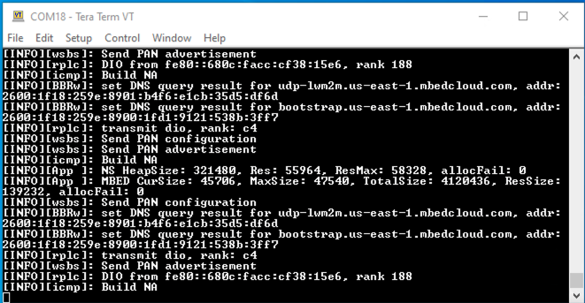 Border router serial output
Setting up the Wi-SUN devices
To set up the Wi-SUN devices:
-
Clone the
mbed-cloud-client-example:git clone https://github.com/PelionIoT/mbed-cloud-client-examplecd mbed-cloud-client-example -
Deploy sub-libraries:
mbed deploy -
Select the toolchain:
mbed toolchain GCC_ARM -
Download a developer certificate from Device Management Portal.
-
Copy the
mbed_cloud_dev_credentials.cfile to the root folder of the application. -
Set the mesh network name in the
"mbed-mesh-api.wisun-network-name"field of thembed_app.jsonfile.The mesh network name can be any value, but it must be identical to the mesh network name you set for your border router.
-
Create update-related configuration and credentials using the
manifest-tool v2.2.0 or laterPython package:manifest-dev-tool init --access-key <Device Management access key>Note: When you create a firmware update image for a deployed device, you must use the same update-related configuration and credentials (update private key, public key certificate,
update_default_resources.cand configuration files) you used in the original device firmware image. Therefore, you need to skip running this command because your environment should be already initialized. -
Compile the application referencing the configuration file with Wi-SUN settings:
mbed compile -m NUCLEO_F429ZI --app-config mesh_wisun.json
Running the Wi-SUN devices
-
Find the binary file
mbed-cloud-client-example.binin theBUILD/<TARGET>/<TOOLCHAIN>folder. -
Copy the binary to the USB mass storage drive of the development board. It automatically flashes to the target MCU. When the flashing is complete, the board restarts itself.
If it does not restart automatically, press the reset button of the development board.
-
Open the serial connection, for example with PuTTY.
Advanced configuration
-
Configuring the Wi-SUN network name:
You can specify your own network name (
mbed-mesh-api.wisun-network-name) for Border router and router application in their respective application configuration file. With different network name you can create multiple different Wi-SUN networks. -
Configuring data rates:
You can configure different data rates used by the Wi-SUN network by changing operation modes and class. These configurations need to be the same for all devices in the network.
From the application configuration file, modify these fields:
mbed-mesh-api.wisun-operating-classandmbed-mesh-api.wisun-operating-mode.For example, values for North America regulatory domain with FSK modulation are:
Regulatory domain Operating class Operating mode Data rate 1 1 0x1b 50kbs 1 2 0x03 150kbs 1 3 0x05 300kbs -
Configuring the Wi-SUN protocol stack heap usage:
You can configure the Wi-SUN protocol stack with different amounts of memory. For routers, the memory can vary from 32KB to 128KB.
Some of the special requirements that require larger amount of memory are:
- Large network size.
- Large data amounts from applications.
- Low packet drop requirement.
- Last gasp success rate requirement.
Izuma Border router requires memory mainly based on the network size. Roughly 650B of RAM for every device connected.
For basic operations and generic routing capability, 80KB is the minimum amount required.
Example memory sizes for border router:
- 320KB of RAM is good for a 200-device network.
- 500KB of RAM is good for a 650-device network.
- 4,000KB of RAM is good for a 6,000-device network.
You can configure memory size by modifying
mbed-mesh-api.heap-size.
High data rate and OFDM modulation support
The Wi-SUN network stack supports OFDM modulation for North American (0x01) and Brazilian (0x07) regulatory domains using channel plan IDs 1, 2 and 5. You must replace the existing operating mode and operating class with the PHY mode ID and channel plan ID in the application configuration file.
Remove existing FSK configuration
```
"mbed-mesh-api.wisun-regulatory-domain"     : "3",
"mbed-mesh-api.wisun-operating-class"       : "2",
"mbed-mesh-api.wisun-operating-mode"        : "3",
```
Add OFDM configuration by selecting regulatory domain and datarate
You can modify the OFDM configurations by adding:
mbed-mesh-api.wisun-regulatory-domainmbed-mesh-api.wisun-channel-plan-idmbed-mesh-api.wisun-phy-mode-id
| Regulatory domain | Channel plan ID | PHY mode ID | Data rate | Info |
|---|---|---|---|---|
| 1 | 1 | 84 | 150kbs | North America |
| 1 | 1 | 85 | 200kbs | North America |
| 1 | 1 | 86 | 300kbs | North America |
| 1 | 2 | 68 | 300kbs | North America |
| 1 | 2 | 69 | 400kbs | North America |
| 1 | 2 | 70 | 600kbs | North America |
| 1 | 5 | 34 | 400kbs | North America |
| 1 | 5 | 35 | 800kbs | North America |
| 1 | 5 | 36 | 1200kbs | North America |
| 1 | 5 | 37 | 1600kbs | North America |
| 1 | 5 | 38 | 2400kbs | North America |
| 7 | 1 | 84 | 150kbs | Brazil |
| 7 | 1 | 85 | 200kbs | Brazil |
| 7 | 1 | 86 | 300kbs | Brazil |
| 7 | 2 | 68 | 300kbs | Brazil |
| 7 | 2 | 69 | 400kbs | Brazil |
| 7 | 2 | 70 | 600kbs | Brazil |
| 7 | 5 | 34 | 400kbs | Brazil |
| 7 | 5 | 35 | 800kbs | Brazil |
| 7 | 5 | 36 | 1200kbs | Brazil |
| 7 | 5 | 37 | 1600kbs | Brazil |
| 7 | 5 | 38 | 2400kbs | Brazil |
Note: ST X-NUCLEO-S2868A2 doesn't support OFDM modulation. OFDM configuration has been tested with the Microchip ATREB215-XPRO radio transceiver.
Sending critical alerts during power loss (last gasp)
If a critical situation occurs in which a device (or the whole mesh network) is at immediate risk of losing power, Device Management Client can go to an alert() state to conserve bandwidth to send critical messages.
This requires applications that:
- Are battery powered.
- Can detect loss of main power.
During the alert() state, the device stops sending all automatic messages. Only the application can trigger notifications. Because the alert() is considered a critical situation, the device only sends the minimum amount of information to conserve the network bandwidth, so other devices can send their critical messages.
We recommend you configure the notification resource to perform non-confirmable message sending to remove the need for server-side acknowledgments and retransmissions of data.
When Device Management Client sends notifications in the alert() state, it marks the packages as high priority. The mesh network then prioritizes the delivery of these messages through the network and holds lower-priority messages until the high-priority traffic ends.
See the documentation for alert() and non-confirmable notifications on how to enable and use the client features from your application. This means any confirmable messages the devices send don't receive acknowledgments from Izuma during this time.
Factory provisioning of Wi-SUN devices
We support factory provisioning of Wi-SUN devices. For further details, contact our sales team or your customer representative.
Network management features for Wi-SUN devices
We support advanced Wi-SUN network management features. For further details, contact sales or your customer representative.
Validating
After the border router is powered on, wait appromiately 10min until the mesh network forms. The time to form the network can vary.
If your devices are connected directly to your computer, you can view their serial terminal to determine whether they have connected to the network and registered with Pelion.
After the devices register, you can view the terminal to see their Device ID.
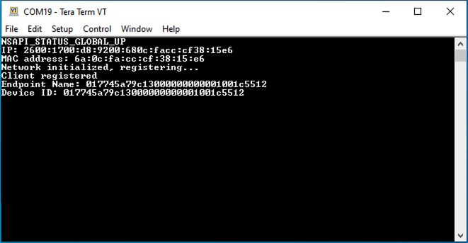 Wi-SUN device serial output
To validate the formation of your Wi-SUN network and the registration of devices to Device Management, open Device Management Portal, and check the devices have been registered:
- Go to Device Registry.
- Click on the Device ID for your devices.
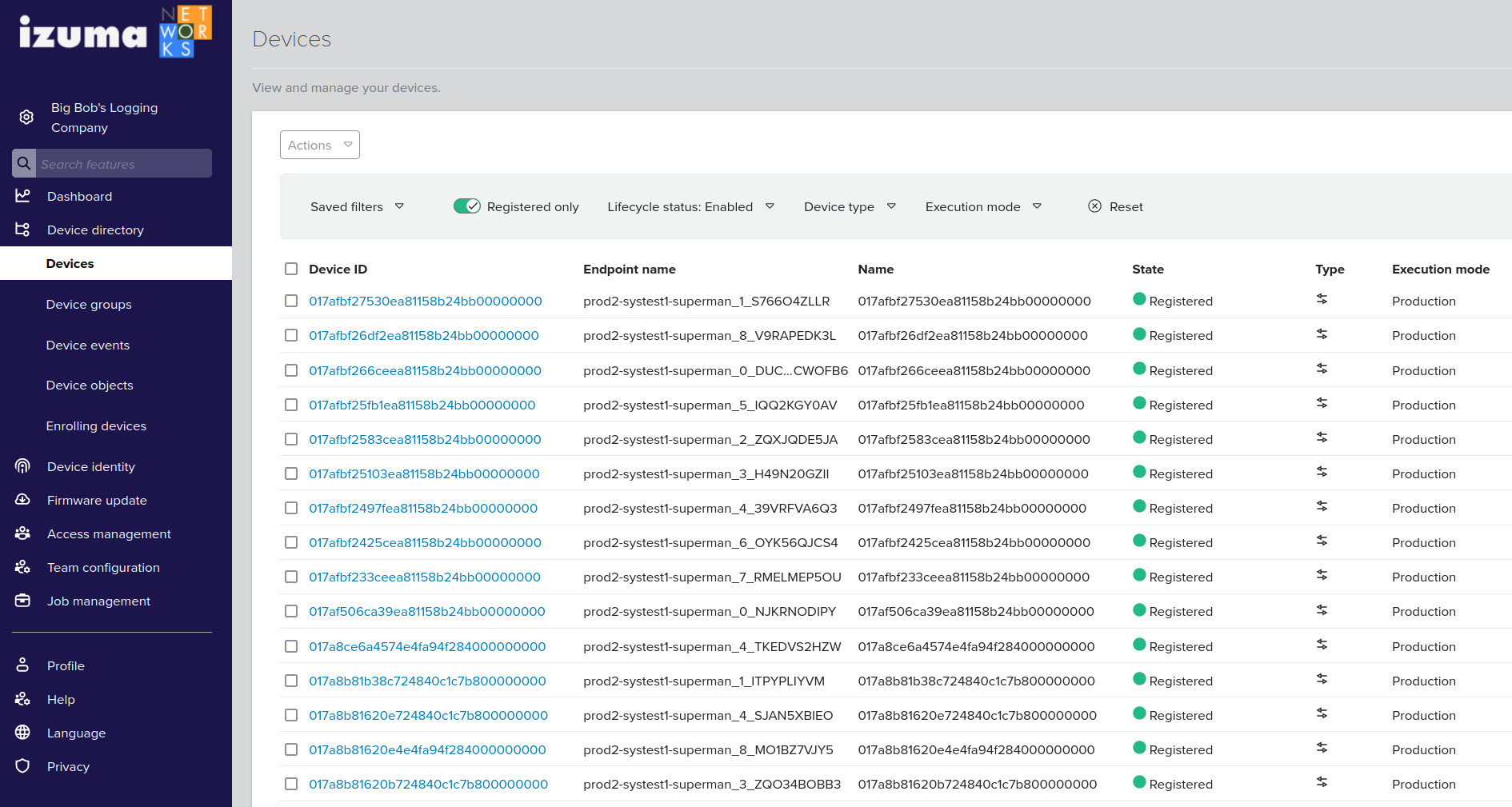 Devices in Device Management Portal
Network management
Izuma Device Management enables monitoring of the mesh network as well as the ability to update the firmware on devices using unicast or multicast updates. Contact a Izuma representative for details.
Deploying larger-scale networks
This tutorial provides an overview of deploying a small-scale network for testing. When deploying larger-scale networks, you need to ensure the MAC/Ethernet addresses the devices use are globally unique.
Globally unique MAC address required
In RF signaling, the radio EUI64 MAC address must be globally unique, or the devices can't operate in the same region. You can do this using a separate chip on your own EUI64 range. The Ethernet address (EUI48) must also be unique.
For small-scale testing, use TRNG-randomized EUI64 and EUI48 values. For larger-scale deployments, you must ensure address uniqueness. For more information about obtaining globally unique MAC/Ethernet addresses, please see the IEEE FAQs.
Unique Wi-SUN certificate required
Note: When you go to production, please do not use the example Wi-SUN certificate files provided without modification due to security reasons.
For testing, you can use the Wi-SUN certificate definitions file configs/wisun_certificates.h. However, for production you must generate your own Wi-SUN certificates file and place in the same location.
Ensure required Wi-SUN certificates (in file wisun_certificates.h) are valid (WISUN_ROOT_CERTIFICATE, WISUN_CLIENT_CERTIFICATE, WISUN_CLIENT_KEY) and match the settings you are using with the border router. Invalid certificates or certificates that don't match prevent mesh network formation.
Test configuration for small-scale testing
Both the pelion-border-router and mbed-cloud-client-example repositories have custom targets with the appendix _AGGRESSIVE, which preconfigures several settings to speed up the device registration and multicasting performance. This is suitable for testing with five or fewer devices in single-hop networks. You must use the same configuration for the whole network. Mixed configurations are not supported.
Compiling the Izuma border router in an aggressive profile:
`mbed compile -m DISCO_F769NI_AGGRESSIVE`
Compiling the Mbed Cloud Client example in an aggressive profile:
`mbed compile -m NUCLEO_F429ZI_AGGRESSIVE --app-config mesh_wisun.json`
Tuning of network parameters required
Optimize the DNS API configuration to fit for high-latency networks. If the client can't connect to Device Management due to DnsResolvingFailed errors, we recommend you fine-tune the Mbed OS DNS API configurations. The Mbed OS defaults are more suitable for low-latency networks. For a network of 100 connected devices, specify, for example:
```
"nsapi.dns-response-wait-time"              : 100000,
"nsapi.dns-total-attempts"                  : 3,
"nsapi.dns-retries"                         : 3,
```
Troubleshooting
This is a list of possible issues and solutions to them.
Verifying correct software components and configurations
Ensure:
- Both the border router and router nodes are using the same Mbed OS version.
mbed-mesh-api.wisun-network-name is identical in the network.Additional tools
You can use an Ethernet and RF sniffer to capture traces and then analyze them using Wireshark.
Use a managed switch to capture all traffic through the Ethernet interface. You can configure the switch to mirror all traffic to a single port connected to a computer running Wireshark.
Registration failing
If the device does not register successfully to Izuma Device Management, check the soldering is done properly.
To enable traces, modify the application configuration file:
mbed_app.json for the Izuma Border Router.
"mbed-trace.enable": true
Then ensure you don't see this error in the logs:
[ERR ][s2lp]: Failed to change state from 0 to: 30
A Failed to change state error either indicates an antenna circuit failure or a communication issue between the S2-LP transceiver and MCU.
First, check your soldering, and make sure the resistor is properly connected to R6. If you still see the issue, the antenna may not be suitable for use with this configuration.
Problem connecting to Device Management after forming the Wi-SUN network
When the Wi-SUN network has formed but the registration to Device Management is failing, make sure the device has received a routable global address. There should be a NSAPI_STATUS_GLOBAL_UP trace in the logs:
[INFO][plat]: NSAPI_STATUS_GLOBAL_UP
IP: fd00:7283:7e00:0:90af:a769:ada8:9f3c
MAC Address: 92:af:a7:69:ad:a8:9f:3c
If the address of the device is in the form fc00:: or fd00::, the address is a Unicast Local Address (ULA) and not globally routable. This can be an indication of the backbone connection from border router not working properly.
In some configurations in which the Wi-SUN network is behind a VPN tunnel or an On Premises deployment, the ULA address is fully functional and there are no issues. Check the address to which the devices are assigned and make sure it matches the deployment type.